This past week was one of much work and little visible progress. On the construction site, the masons gave their new saw some more exercise, but it developed a wobble and needed to be rebuilt. By the end of the week they had managed to build two two-course corners at the foundation level. One of the mitered corners is pictured here:
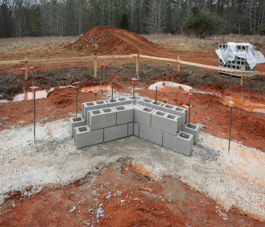
Actually, the picture shows several features of the planned masonry construction.
First, you will notice that the rebar does, in fact, come up through the CMU holes. When the blocks are filled with cement, the rebar will bind the blocks to the footings. Second, you will note that outer edges show only full- and half-length blocks, even in the mitre joints. The inner edges show 1/4 and 3/4 length blocks at the miter joints, and full- and half-length everywhere else. Third, you will note that the blocks of the inner walls are perfect translations of the blocks of the outer walls (except where the inner blocks form corners, in which case full blocks become 3/4 length blocks and half-length blocks become 1/4 length blocks). In order to make the blocks land at these simple fractional values, the walls are spaced such that the diagonal of the miter joint is precisely 24″. The perpendicular thickness of the walls is 20.785″ (24″ × cos 60°), and the space between the blocks is 5.535″ (after subtracting 2 block widths of 7-5/8″). It’s kinda neat how transcendental numbers can come into play and then cancel out to make everything integral and simple fractions again.
As the masons work out corner-building techniques, I’ve been spending nights and weekends on some comprehensive shop diagrams showing every wall, every masonry course, and every block type, material, mitering, and orientation. If the diagrams are correct, we’re at approximately 15,000 blocks at screed level or above, with about 1,000 blocks like the ones pictured above going into the foundation. For point of reference, 16,000 blocks stacked end-to-end would be four miles long!
Here are two examples of the shop drawings (there are 22 total pages!):

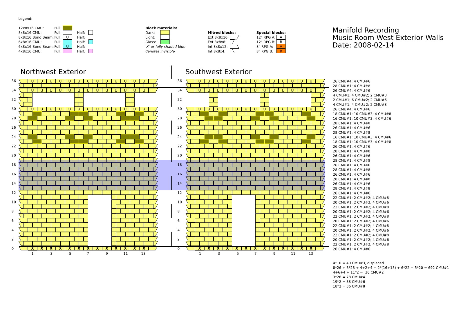
Needless to say, this was a very “detail oriented” job, and took many hours of checking and re-checking block types and placements. The payoff, hopefully, is that we can position the right materials in the right places and minimize the amount of handling of the blocks on the worksite, which in turn will mean more beautiful walls. And of course we hope that we end up putting the door frames where the door frames are supposed to be. After all, we really are setting the design in stone…
At this point I should also give some props to the open source community. The programs I used for making the shop drawings were inkscape and GNU Emacs. This was my first real project using Inkscape, and it worked like a champ. When it didn’t (or when I was too much of a bum to make it look like a champ), I used Emacs to edit the XML files and get everything straightened back out again. It is wonderful to have the choice to both work with graphics and snapping when that works, and then use Emacs’s powerful search-and-replace functions when a better idea comes along and you want to change everything the same way in 22 files.

4 thoughts on “Construction photos: week 6 (first mitered corners and block diagrams)”