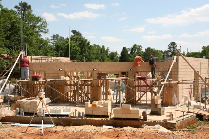
The weather forecast for this week was again anticipated to be terrible, but in the end things shaped up nicely, with only Monday lost due to rain. The major objectives of the week were met: the establishment of the North bond beam and the placement of the massive (1100 lb/500 kg) South steel beam. Read on to see how it’s all taking shape…
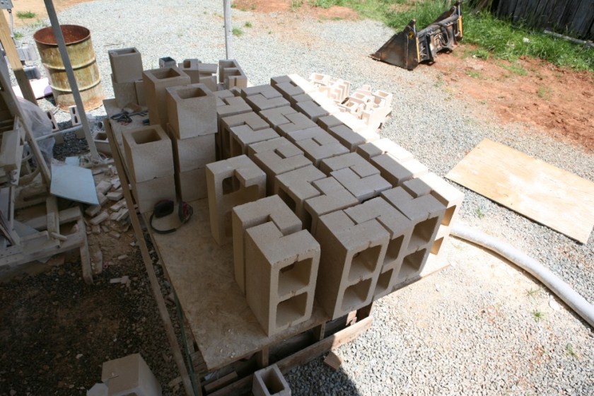
If you read last week’s second entry, you know that the North bond beam is going to be made from three courses of blocks: a V-shaped bond beam block at the base, custom-cut blocks in the middle (which allow the concrete grout to flow up/down, east/west, and north/south), and differently custom-cut blocks on the top (allowing the concrete to basically flow up/down and east/west). By the end of last week, most of the middle blocks had been put into position on the outer wythe. Here are the 30+ blocks that will complete the inner wythe, still on the cutting table:
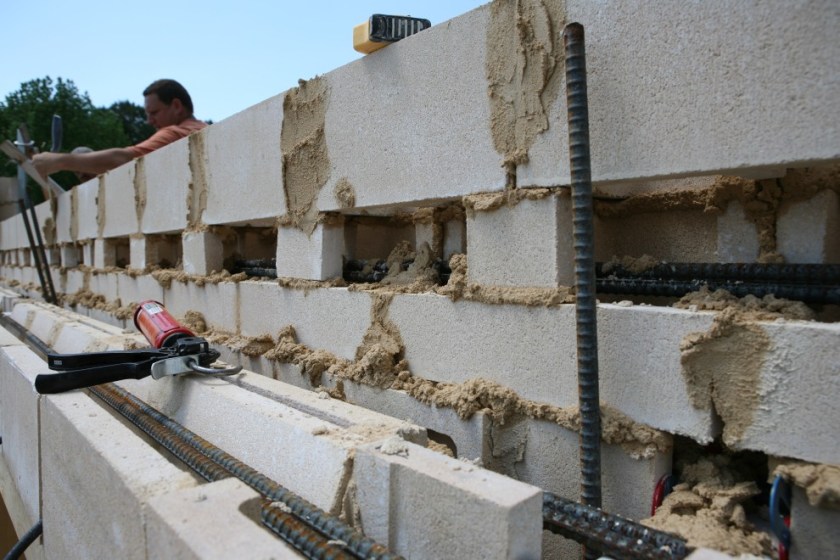
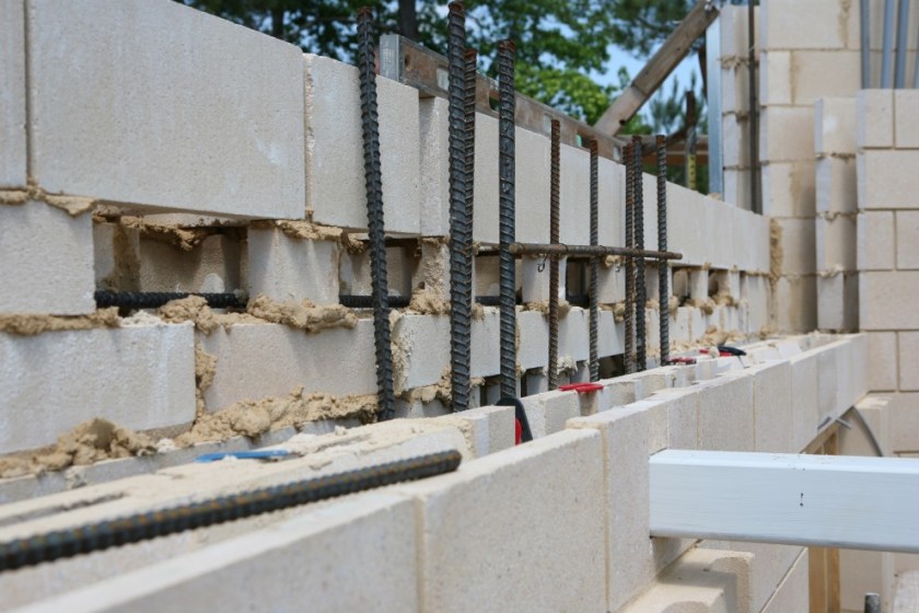
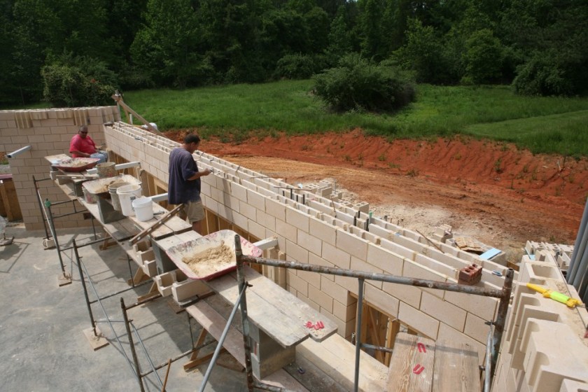
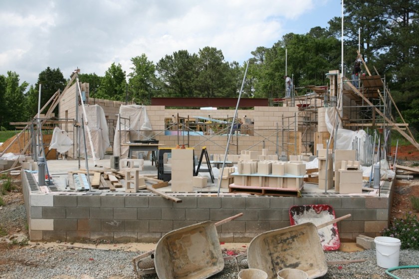
Here’s the outer wythe almost completed. The inner wythe will be a mirror image to it, and you can see how the concrete can flow north/south across the cut-out faces of the middle course:
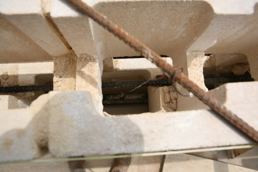
Here’s a view that shows a detail of the middle course of the bond beam (complete with its pair of #5 steel rebar elements):
More steel:
And more steel:
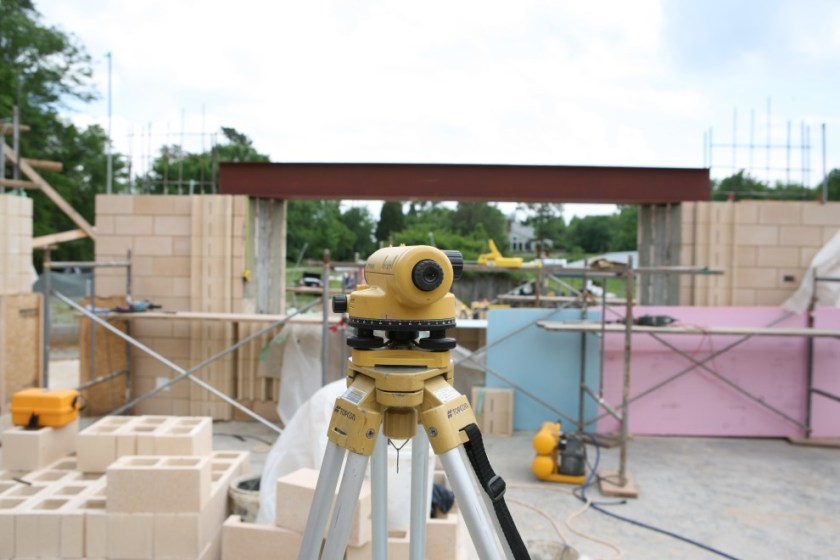
From the other side it just looks like a normal part of the building:
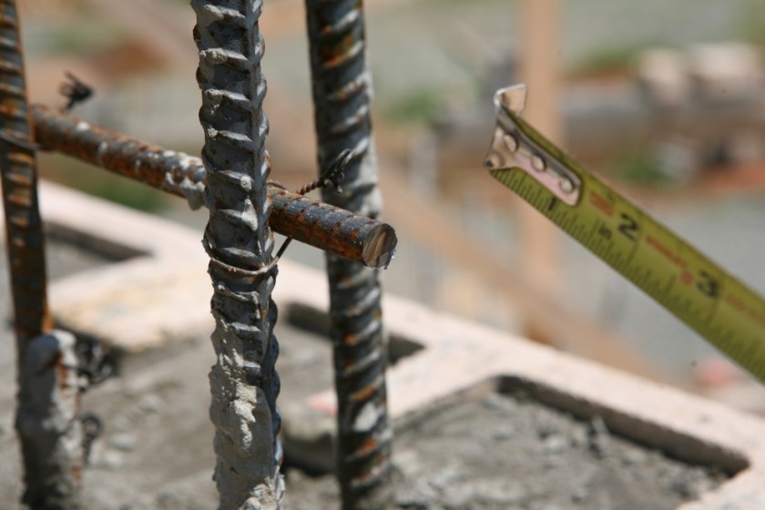
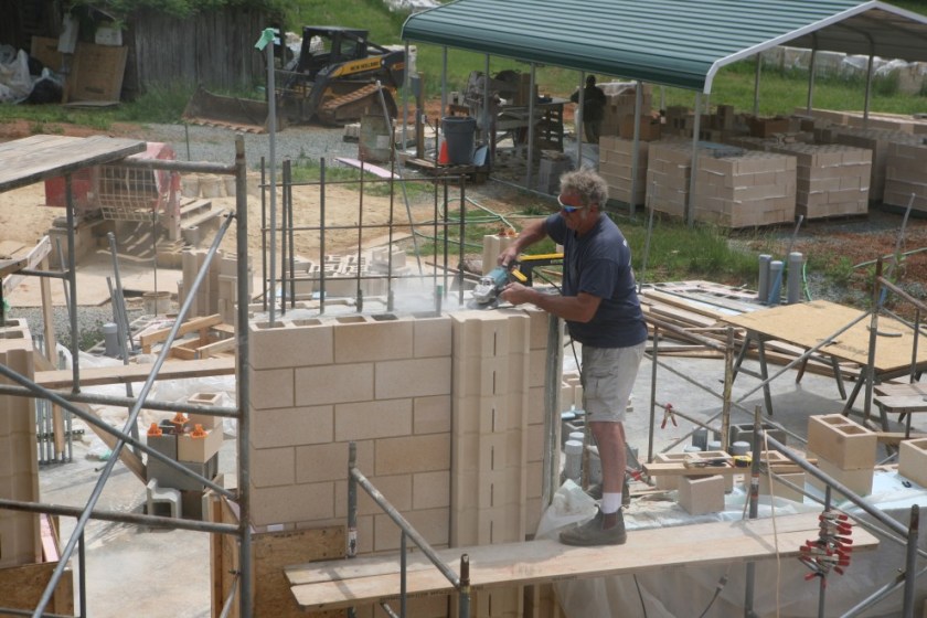
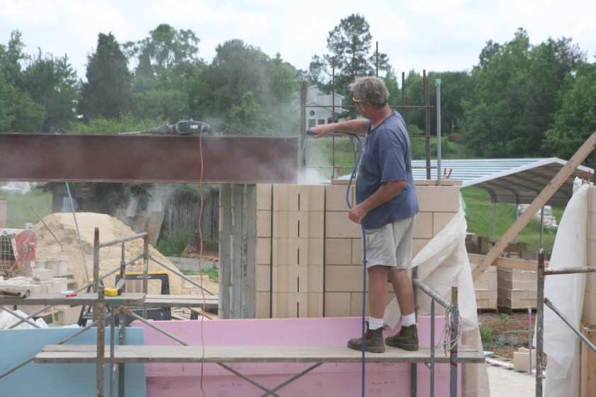
Meanwhile…on the other side of the building sparks are flying as Kevin cuts off some rebar that’s going to be interrupted by the massive South steel beam:
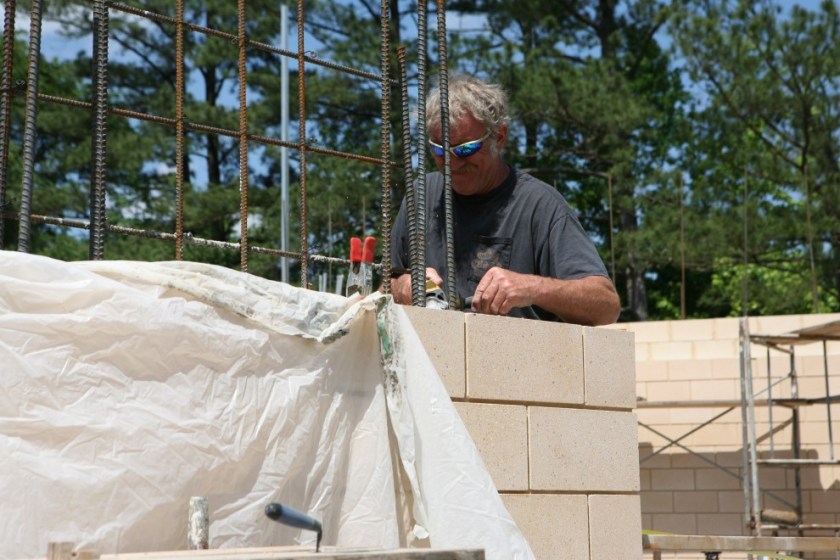
The freshly cut results:
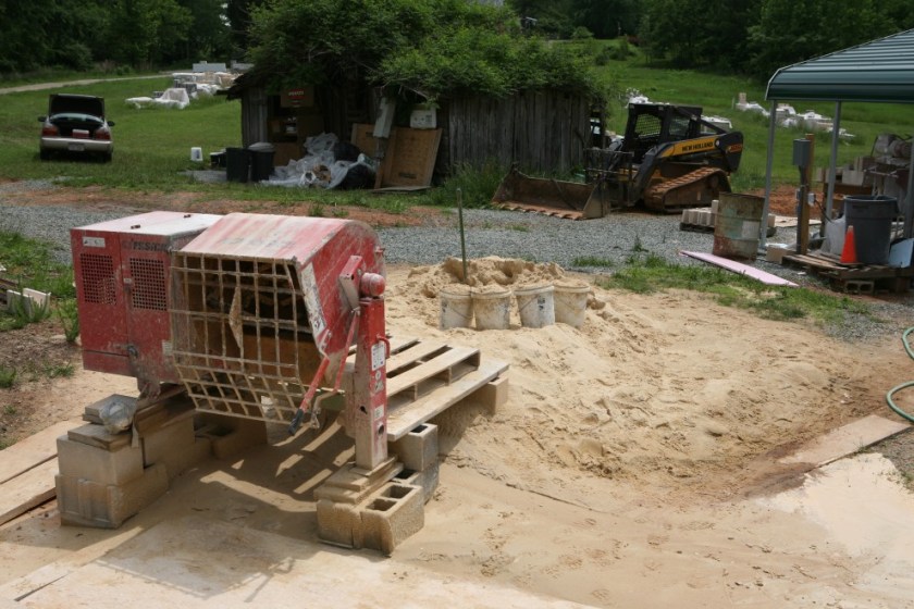
With all the progress, we’re getting low on sand for the mortar:
One call later, problem solved:
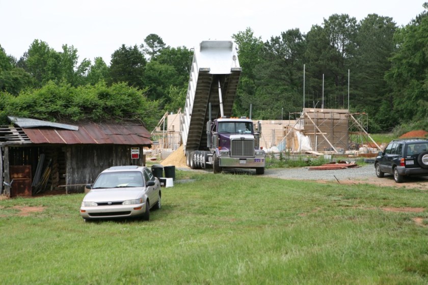
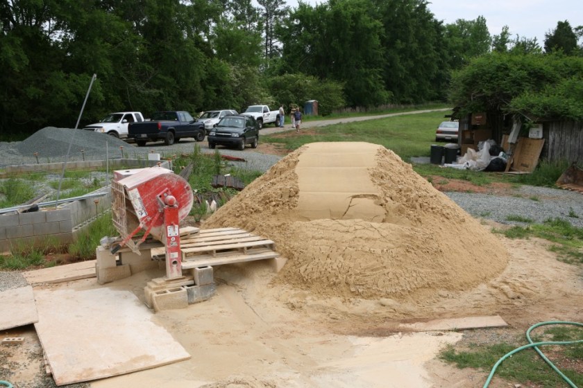
Nice!
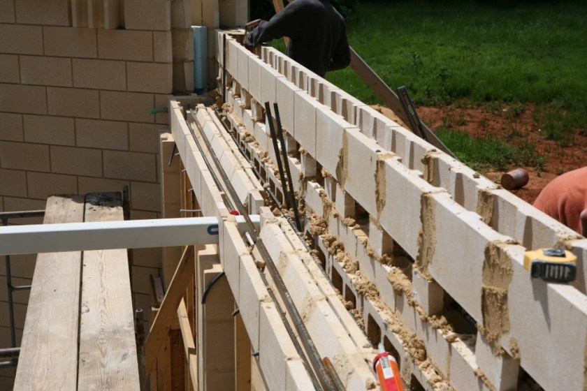
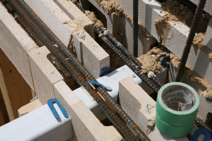
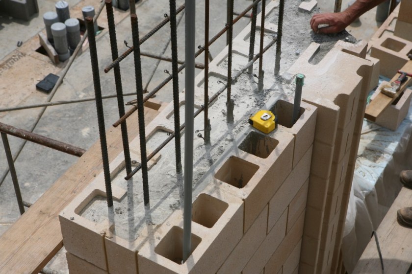
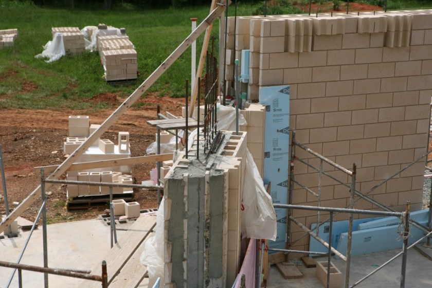
In the mean time, the other side of the bond beam is laying up nicely. The metal bars are holding wires that hold the steel rebar in position. When it comes time to grout everything the rebar wants to have a minimum of 1″ of concrete surrounding it. These strategically-placed suspension rods accomplish that without disturbing the final integrity of the bond beam:

(Note also in the above picture you can see that our grout sand and gravel piles were also refreshed. They were getting pretty low, too.)
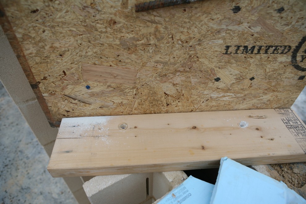
Here’s a detail of the suspension rods (looking down):
It’s nearly two feet down from the suspension rod to the inside bottom of the bottom block.
You may wonder, as I did, why suspend the rebar instead of just putting a “chair” underneath it every 4-6 feet. The answer is that anything you put under the steel and on top of the concrete block functions like a crack in the beam. You don’t want to build a 34′ long bond beam with 9 cracks in it, so you want to have the rebar suspended. After the concrete grout is poured, the wires can be clipped off at the top and the rods reused for other purposes.
From the inside, too, the bond beam looks like a normal part of the building:
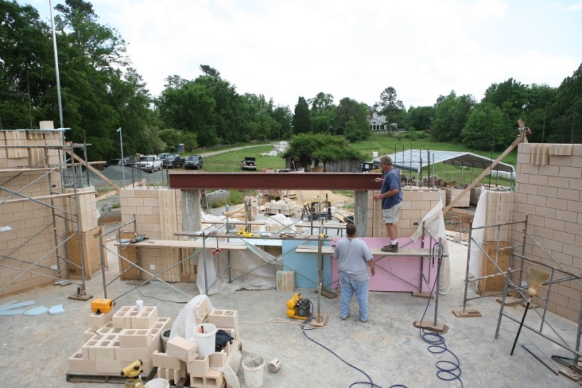
Moving back over to the South wall where the steel beam is going to go, Kevin forces the blocks to be level. The steel beam is going to carry a 16′ long stretch of wall that’s nearly 16′ tall, and so any deviation from level is going to put stress on the beam that we don’t want. Kevin sands off some high spots that would normally be invisible because they would be hidden in the 3/8″ mortar joint:
Now we’re level (or we can build up to level):
With the wooden dam removed (detailed in the first of last week’s entries), we can now see how the concrete has flowed to hold in place the small corner blocks that otherwise have little to hold onto:
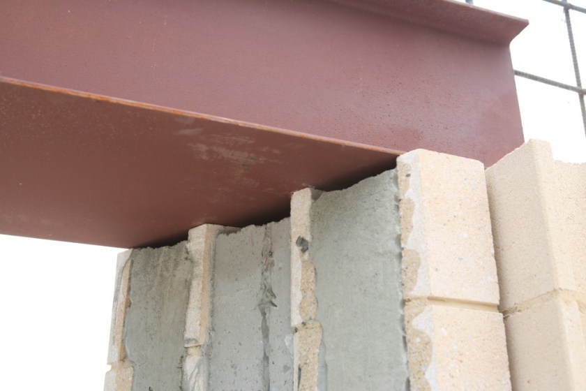
The large steel beam has been placed!
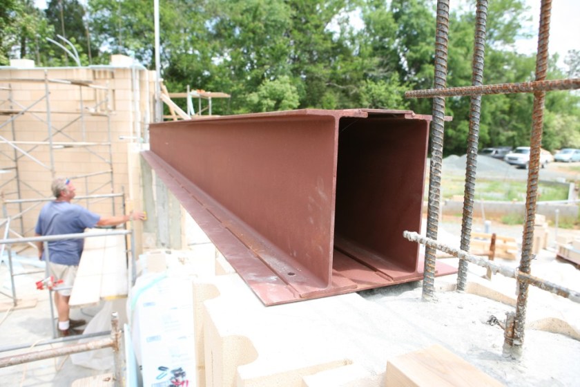
And it’s level from end to end:
Here’s how it’s going to work: the beam is 16″ tall with a 1/4″ bottom plate that’s 19″ wide. There will be two courses of 4″ blocks placed north and south of the steel beam, concealing it. Then the inner and outer wythes will continue to the ceiling using 8″ blocks. The 8″ blocks will balance at least half their weight on the 4″ blocks (which are twice as strong as half an 8″ block) and the remaining weight will be borne by the steel beam. Since the beam is actually a double I-beam, that means that each wythe delivers somewhat less than half its weight to an I-beam that weighs in at 22 lbs per linear foot.
Holes are drilled for the anchor bolts, and then all the dust is blown out so that we get a nice clean fit:
Looking up:
Everything’s nice and centered:
Tomorrow, the anchor bolts will be epoxied, the grout for the bond beam will be poured, and both will cure over the weekend.

I live not far from you (just outside of Pittsboro,nc). I have a private studio there, not as nice as yours is going to be. Mine is a Control=15x20x10 live room=20x30x22 Neve console, pro-tools, otari 24, mics and outboard out the ying-yang. I am a researcher at UNC by day. Best of luck in your construction. I enjoy you blog.